Simple 12V 9V 6V Motor DC Speed Control with PWM mode
As the name suggests, the purpose of the L293D motor driver is to drive DC motors. The L293D is a popular motor driver IC that has a built-in H-bridge circuit that can drive two DC motors simultaneously. It can supply up to 1A of current and voltages from 4.5V to 36V. This means the L293D motor driver is ideal for building multi-wheel robot.
12v Dc Motor Controller Circuit Diagram Wiring Flow Schema
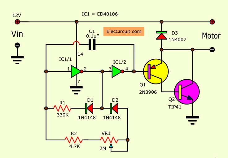
These are 12-volt DC variable-speed motor controller circuit using CMOS. They use the principle of PWM motor control mode. We can adjust the speed of 12V small motor. Even 6V or 9V Motor, this can be used, too. It is easy and uses a few components that IC digital and transistor driver as main. Table of Contents hide The motor speed control method
12v Dc Motor Circuit Diagram
An integrated H-bridge driver is a circuit with built-in power transistors. Despite the simplicity and reliability of its design, the gate driver IC is intended for low-voltage and low-power applications.. H-bridge DC motor controller circuit . BDC motor controller circuit design depends on the type of signal, power regulation, control.

How To Make A Simple Dc Motor Control
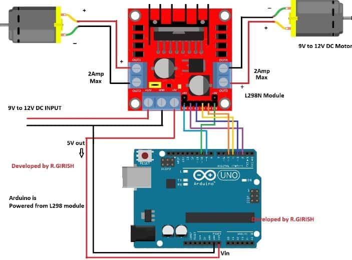
It can control the speed and spinning direction of two DC motors. In addition, it can control a bipolar stepper motor, such as the NEMA 17. If you want to learn more about it, check out this tutorial. Control Stepper Motor with L298N Motor Driver & Arduino
Electronic arduino How to control the speed of a 12V DC motor with
Here we will discuss one of the most commonly used and efficient way to drive DC motors - H-Bridge circuit. Motor Driving.. This has some interesting implications - a 3V motor can be driven using a 12V supply using a low duty cycle since the motor sees only the average voltage. With careful design, this eliminates the need for a separate.
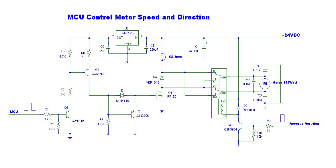
MCU system Controller 12V DC Motor Speed and Direction using IRF150
DC Motor Speed Control - LAB. Learn how to use PWM signal to control the speed of a DC Motor. Also, you should be using an L293D Motor Driver IC in order to control the direction of motor's rotation. Push buttons should be used to specify the speed 0%, 50%, 75%, 100% and an extra button for reversing the direction of rotation.
12v 5a Dc Motor Speed Control Circuit Diagram
When you power the 12V DC motor by a 12V power source: 12V and GND to the positive wire and negative wire, respectively: the DC motor rotates at maximum speed in the clockwise direction 12V and GND to the negative wire and positive wire, respectively: the DC motor rotates at maximum speed in the anti-clockwise direction
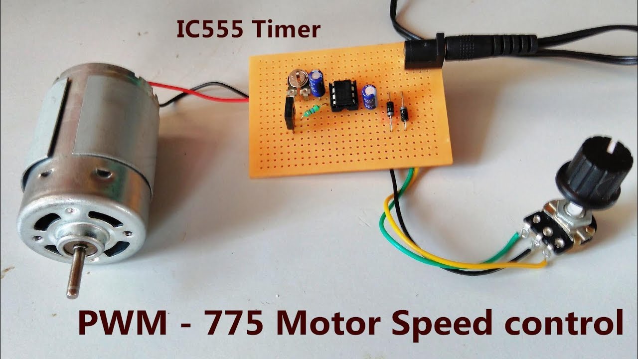
IC555 PWM 775 Motor Speed Controller 0.5v to 12v DC POWER GEN
This article will discuss simple methods to select components for a pre-driver/power MOSFET circuit, and the resulting performance of the system. Start with the Motor. To design a DC motor drive — whether it is for a brush motor or a three-phase brushless motor — the motor characteristics will determine the design details of the drive.
.PNG)
12V 63RPM 20kgfcm DC Geared Motor with Encoder MG Super Labs
The L293D is a 16 pins motor driver IC, and you can control two DC motors or one stepper motor under 600mA current.. and Pin 10 (Input_3), Pin 15 (Input_4) control the switches of the H-Bridge circuit inside the L293D IC. Input_1 and Input_2 have connected two terminals of DC motor_1used to control the direction of motor_1.. however, for.
L298N DC Motor Driver Module Explained Homemade Circuit Projects
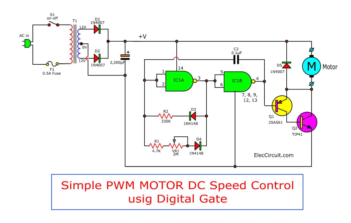
The circuit is designed to work with 12 volt DC motors having a peak current usage of below 5 amp. The mains AC supply is provided through the on/off switch S1 to the primary winding of the isolation and step-down transformer T1.

12v Dc Motor Controller Circuit Diagram Wiring Diagram
An H-Bridge motor driver circuit is an H-shaped circuitry in which the DC motor is hooked through 4 Switches/Transistors between the power rails. Arduino BTS7960 DC Motor Driver Code Example. In this example project, we'll use an Arduino + BTS7960 DC Motor driver to control the direction and speed of a 12v DC Motor. A push button will be.
555 PWM DC motor controller circuit
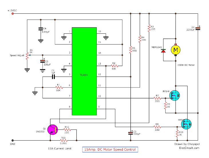
This is a 12V DC motor speed control PWM circuit. Which using a TL494 (Switchmode Pulse Width Modulation Control IC) is a base for control DC Motor with pulse. Please detail more: - For Control speed motor 12V 150Wmax 15A. - R6 adjust speed motor. - Driver Motor by Mosfet IRFZ48.x 2pcs. - Control at Frequency 100HZ
12 volt DC motor speed controller with pulse Electronic projects circuits
A typical DC motor will have the following characteristics: Torque (in kg.cm) Rated Rotation Speed (RPM) Rated Full-Load current (e.g. 2A) Rated No-Load current (e.g. 0.2A) Rated voltage for operation (e.g. 12v) 1- DC Motor Direction Control
DCMotor Driver circuits
A Nexperia demo application which showcases how MOSFETs may replace relays may be seen in Fig. 3. These were used in controlling the mirror power-folding mechanism using 12 V or 24 V H- bridge DC motor control. As can be seen, the relays were replaced with MOSFETs in the LFPAK33, LFPAK56D and LFPAK56 small SMD packages.

12v Dc Motor Controller Circuit Diagram Wiring Diagram
Multi MOSFET Driver IC: Infineon's TLE9210x is a family of MOTIX™ Multi MOSFET Driver ICs, designed to control up to eight half-bridges (up to 16 n-channel MOSFETs) with one packaged device. Target applications involve automotive DC motor and solenoid control, such as power seat modules, power closure systems and many more. System Benefits:
how to make Simple dc motor speed control circuit, electronics projects
You can use any 12v speed controller that accepts a PWM signal. There are many such controllers available. Check eBay and google. What you will be doing is using the PWM signal from the arduino to control a speed controller that is "regulating" the voltage to a motor. This way the power source for the motor is completely independent from the.